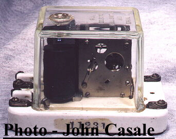
Installation of additional selectors, except on such sets as specifications provide them, must be approved by Vice Pres. Traffic before reqn. is written and the approval noted on the reqn. Reqns. for maintenance purposes must be approved by the head of department in charge of the maintenance. Used to close a local circuit by transmission of a predetermined set of direct current impulses over a line. An electromagnet whose armature drives a gear train in such a way that if its predetermined code is received, the train closes a contact, but if any other impulses are received, the contact gear drops out of step. Mechanism is set on a porcelain base and covered with a glass case. L--6", W--4", Ht--4"".
| Model | Resistance | Current | ||
| Series | Parallel | Series | Parallel | |
| D | 8 | 100 | ||
| F | 100 | 25 | 40 | 90 |
* If needed for a new office having no code assigned state "Code unassigned" and also whether for W. U. or railroad office.
++++++++++++++++++++++++++++++++++++++++++
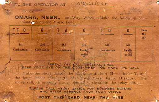
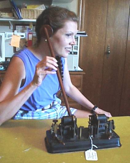
John Casale sent a set of instructions for a Gill Selector that was used in O'Neill, Nebraska to get the attention of a Western Union operator via the gill selector in Omaha, Nebraska.
* When changing local circuit voltage, complete new sets should be ordered.
Ordinary telegraph sounder for use on local circuits. Electromagnet with armature set on a pivoted sounding bar. Bar plays between two legs of U-shaped anvil, stop screws being provided for adjustments. Mechanism is set on wood base. Type 1-B has coils brought out separately to binding posts for either series or parallel connection.
| Type | Resistance | Current | L | W | Ht |
| 1-A | 4 | 250 | 5 ˝" | 3" | 3 ˝ |
| 50 | 110 | Same | |||
| 1-B | 400 (series) | 30 | " | ||
| 100 (parallel) | 60 | " | |||
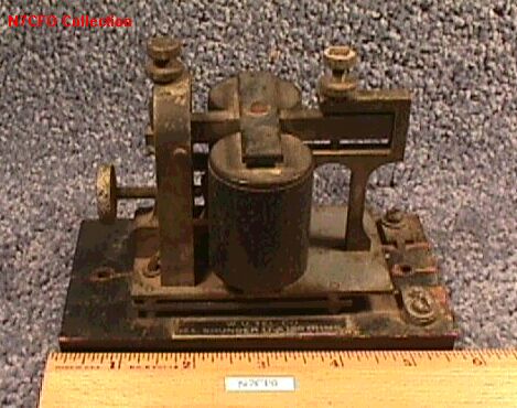
Use on single Morse circuits for operation directly in main line instead of a local circuit. Generally similar to common sounder but of larger size. Coils are moveable horizontally so as to vary air gap between pole pieces and armature, thus compensating for varying line current. Furnished in 30 and 120 ohms, requiring 70 and 40 mils respec. L--5 ˝", W--3", Ht--4".
*15-A type now obsolete had adjustment screw on top of armature, this being only adjustment feature. Resistance 150 ohms.
SOUNDER, MAIN LINE, 17-A.
Used in local circuits where it is desired to repeat the signal into another circuit. Similar in size and general design to #1 sounder, but has contact screws on anvil end of sounding bar. #2 type makes on down stroke while #3 not only makes on down stroke but opens another circuit at same time.
| Type | Resistance | Current | Specn. |
| 2-A | 4 | 250 | E-178-D |
| 50 | 110 | E-178-D | |
| 2-B | 400 (series) | 30 | 767-B |
| 100 (parallel) | 60 | 767-B | |
| 3-A | same as 2-B | 1597-A |
Used where it is desired that operator only shall hear signals. Miniature sounder set in watch case receiver on head band. Cord included.
| Type | Resistance | Current |
| 6230 | 5 | 500 |
| 6231 | 20 | 250 |
| 6232 | 150 | 50 |
Western Electric sold the 6A Secret Sounder
![]()
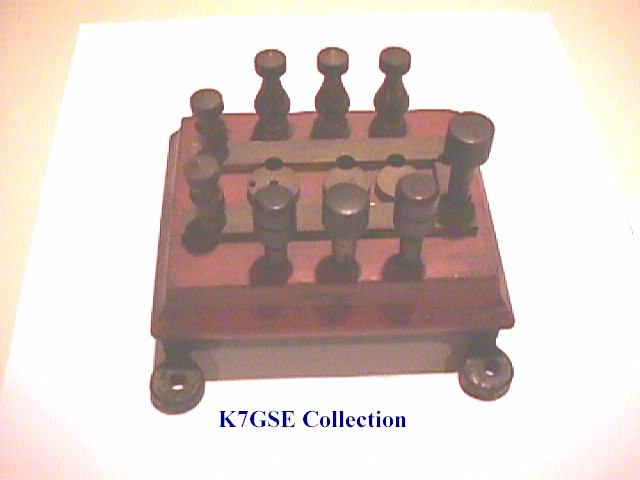
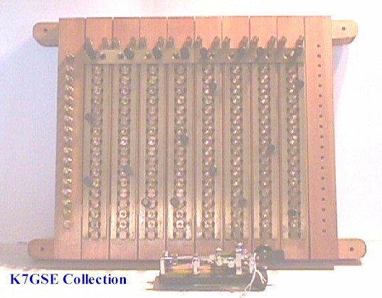
A variety of switchboards were used. They ranged from small models to very large ones.
Sheet metal case with moulded hinged face panel in which jacks are mounted. Protective apparatus is mounted in rear of panel on rear of panel and wires to line and instruments terminate on a block in bottom of box. Opening of hinged panel operates contacts on the block to cut line through and disconnect protectors and jacks, leaving these ports "dead" until panel is closed. Panel can be latched part way open to provide this condition during hours when office is closed.
The units are made in two types, SINGLE and DOUBLE circuit. The first has one panel with five jacks (one for ground) and protection for one Morse wire passing through instruments. As shipped it has it has an internal strap cutting out the instrument leads making the wiring an "AK" circuit. The Double has two panels side by side in one box They are rigidly connected by iron straps, which can, if desired, be removed to open each panel individually. The internal strapping is such that connections can be set up for two telegraph wires or for the various ARA telephone Size: Single--W--4", Ht--6 3/4";D--6"; double--W==8 1/4", Ht--6 3/4", D--6"
3-A unit had same construction as as 1-C, while 3-B is same as 1-D.
Depth 3", otherwise same size as #1 unit.
An angle iron framework with wood top, furnished completely knocked down. Assembles into double sided units 33" by 42" deep any number of which can be assembled together. For each group one Main Unit needed to provide end legs of table, with intermediate units to build up the size required. Main Unit can be recognized by fact legs span full width of table, while those of intermediate unit are only 18" apart. Main Unit top can be identified by 2 pieces 10" by 24", while intermediate includes 1 piece 24" by 42". Filebar 1-A was ordered separately to fit length of each table.
A framework consists of a boxlike skeleton structure (on which the top mounts) and one pair of legs. To complete each row of grouped units, one leg, Morse Table 11-B must be ordered, this item consisting of two uprights, one crossbar, feet, bolts, etc. Each framework, plus the top, provides one Morse position. Tops are linoleum covered, and section back of drop is in one piece so can be removed independently if wiring is to be changed. Front sections can be replaced without disturbing wiring.
Tables are to be set up back to back with 3" separation, this space being covered by a filler on which Filebar 1-A of the proper length is mounted.
*The first issues of this type of table were marked 1-A and had wooden tops.
Used on unit Morse tables #11 type.
An instrument board 8" x 33" of oak veneer, and a typewriter drop and
two side panels of linoleum covered seven ply fir.
* First issues of these tops were of solid wood
Mechanism like a repeating sounder with bar extended beyond trunnion piece to form mounting for a an insulated offset spring contact finger. Contact screw on a separately mounted post strikes finger as transmitter operates. In unoperated position finger touches insulated stud on turned-up end of bar. Has 2 separate 2-point lever switches on base to short out points.
| Resistance | Current |
| 40 | 110 |
| 400 | 30 |
L--8 3/4", W--5", Ht--4 3/4"
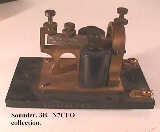
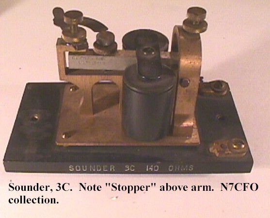
Two pairs of electromagnets facing each other with a single armature set between two spectacle type frames about 1" apart.
#3 type has windings on all four coils connected in series.
#4 type has each pair brought out separately, one pair to be used in a local circuit kept continuously closed. If all coils on a #4 type are connected together externally it is equivalent to a #3.
| Type | Resistance | Current |
| 3-B | 8 | 250 |
| 26 | 110 | |
| 3-C | 400 | *30 (series) 60 (multiple) |
*Coils in series--400 ohms; parallel--100 ohms.
The 4-A type, when used as such, has only half the above resistances, but has been referred to under the same values to allow interchangeability. Iron subbase 8 1/4" by 4 3/4". Overall Ht. 3 5/8".
Note that resistances are one half those of #3 types.
| Resistance | Current |
| 4 ohm | 250 |
| 13 " | 110 |
| 200 " | 30 |
Much similar to Atkinson transmitter but has no contacts at anvil end, and insulating stud at other end is replaced by a contact. 40 or 400 ohm.
Much similar to Atkinson transmitter but has flat contact spring and single pole double throw lever switch. Operating data same as for Atkinson transmitter. 40 or 400 ohm.
Used on Morse tables to concentrate several wires before one position, and on simplex printer tables for test circuits. A two part metal box with 3 jacks set in a composition panel which forms front of box. Top, one side and rear of box are detachable in one piece to afford ready access for wiring. Jacks have springs equivalent to #203-A type, and sleeves are strapped by wire which can be removed when box is not to be used as a cordless jack (as on simplex tables). External connections can be made to either Fahnestock clips or soldering lugs. W--3 1/2", Ht--2". D--4 3/4"
*Type 1-A unit (Specn. 971-A) is similar, except that it had screw terminals, and sleeves of all three jacks were built into a single brass plate, thus making it suitable only for cordless jack service. Type 2-A (Specn. 1808-A) has separate sleeves as in the 2-B type, but terminals are of the screw type as in the 1-A unit.
[NOTE: The spelling of "voltmilammeter" and "milammeter" was copied from the book.]
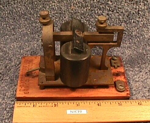
Used in call boxes for furnishing signal impulses. Two toothed brass discs mounted rigidly together. Movement of box gears cause pins of call box to engage tops of teeth as code wheel revolves. Wheels are coded to order in the following numbers, all inclusive. Numbers 512 and up shall be used only when lower ones cannot be used.
| 21 to 25 | 121 to 125 | 212 to 215 | 312 to 315 | 412 to 415 | 512 to 515 | 612 to 615 |
| 31 to 35 | 131 to 135 | 221 to 225 | 321 to 325 | 421 to 425 | 521 to 525 | 621 to 624 |
| 41 to 45 | 141 to 145 | 231 to 235 | 331 to 335 | 431 to 435 | 531 to 534 | 631 to 633 |
| 51 to 55 | 151 to 155 | 241 to 245 | 341 to 345 | 441 to 444 | 541 to 543 | 641 to 642 |
| 251 to 255 | 351 to 354 | 441 to 453 | 551 to 552 | 651 |