Used on messenger call circuits to register calls. A clock work mechanism which is started by movement of the armature of an electromagnet connected into the register leg of the call circuit. Starting of the mechanism draws paper tape through between a thin roller and a "pen" which throws tape against roller when armature operates. Edge of roller is inked by an ink wheel and makes mark on tape each time pen operates. Has two pens and two electromagnets, thus caring for two circuits. Clockwork is in metal case with subbase, coils and pens being on outside. Tape is carried on a bracket arm.
| Type | Resistance | Current | Where used |
| 1-C | 6 | 250 | 26 and 52 volt old style board |
| 1-C | 400 | 50 | All voltages, #2 type units. |
| 3-A | 3000* | 30 | With #3 type units. |
* Resistance of coils is 1000 ohms, balance being added resistance mounted under base. Supersedes 2-A 1900 ohm register, which had 400 ohm coils with 1500 ohms added.
L--10 ˝", W--7 1/4", Ht--6".
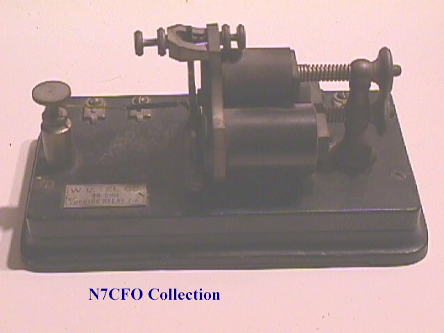
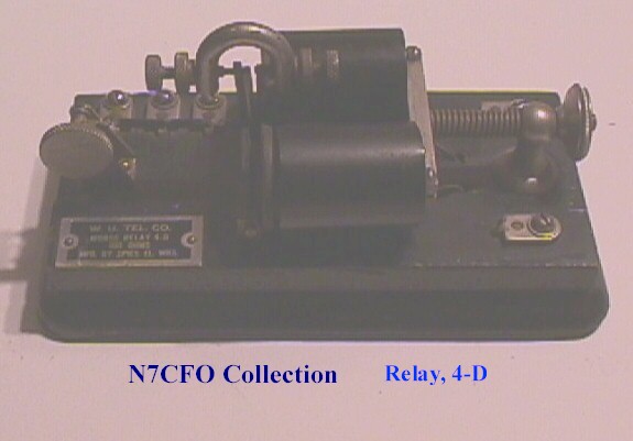
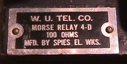
For general use in single Morse operation. Common telegraph relay with pair of adjustable magnets, armature, "goose-neck" contact carrier, all mounted on a wood base. Type 4-B, the oldest model is mechanically larger than the later 4-C and 4-D, and has a higher resistance for a given operating current. The 4-B type was originally made in 35 and 150 ohm resistance, but 150 ohm only is now furnished, the other being superseded by 4-C 25 ohms. The 4-B type must be used wherever space and resistance will permit.
| Type | Resistance | Normal Current | L | W | Ht |
| 4-B | 150 | 40 | 8 1/8" | 4 3/4" | 3 ˝" |
| 4-D* | 25 | 60 | 7 3/16" | 3 7/8" | 3 3/4" |
| 4-D* | 100 | 40 | same | ||
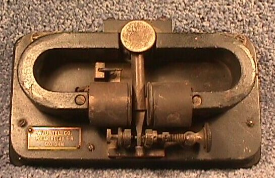
Used on circuits such as quadruplex, central battery duplex, etc., which require a differential non-polar relay. Also used on simplex telephone circuits per Specn. 559. Two pairs of electromagnets, the larger, or main line pair being set side by side, and the upper or holding, pair set one above the other. The line coils are each wound differential, while the holding coils are single wound. A single armature is mounted in the field of both main line and holding coils. Slate base with iron subbase. Resistance--each line circuit approx 250 ohms; holding coil 2000 ohms. L--8 1/4", W--4 7/8", Ht--5 ˝".
* Older relays types 7-A and 7-B had a holding coil of only 230 ohms.
*Two other types of relay, the Frier and the 16-A will be furnished interchangeably as available in stock. The Frier type can be identified by the fact that coils are encased in a brass case, while the 16-A type has a single L-shaped permanent magnet.
Used on printer and other high speed circuits where relay of the 6-C type is not of sufficient speed. A U-shaped magnet with one leg bent upwards to a horizontal position to form mounting for a pair of coils set side by side with armature between them. Each coil has three windings, two main line which are differential--and a third for local circuit. Contacts are set on sliding block. Relay is fastened to a relay mounting 2-A for quick attachment to relay subbase 2-A (ordered separately), and has a cylindrical cover with hinged top in which is set a magnifying glass for viewing the contacts without opening the top. Dia--5 1/8", Ht--5 3/8".
* A few 17-A relays built on the same general principles are also in service.
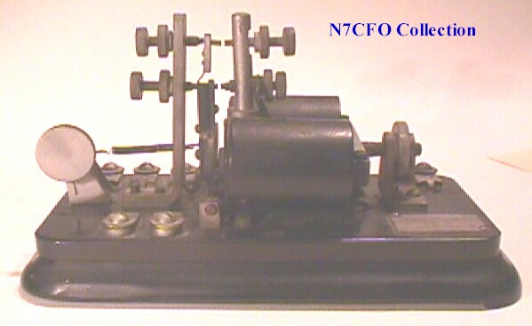
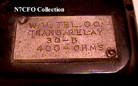
Used on single line repeaters of the front locking shunt contact type. A relay either of the Morse 4-C or 4-D type, or of similar design, with an extra pair of contacts added in order to close two circuits when the relay is energized. One pair closes before the other and this pair is the last to open. Two types are furnished interchangeably, WE 24 or #30 (W. U. Specn.). Each made in two resistance values, 25 ohm or 400 ohm. #24 type is coded 24-C for 25 ohm, and 24-D for 400 ohm, while coding of the #30 is the same for either resistance. Type 30-A (Specn. 1369-A) is made by converting a Morse relay, while type 30-B (Specn. 1888-A) is a direct manufacture. All of these relays have lugs for connection of coils in series or parallel. [30-B label. This relay was made by Liberty Electric Co.]
| Type | Resistance | Current | ||
| Series | Parallel | Series | Parallel | |
| 25 ohm | 25 | 6.25 | 110 | 250 |
| 400 ohm | 400 | 100 | 30 | 60 |
L--7 3/8", W--3 7/8", Ht--5 3/4"

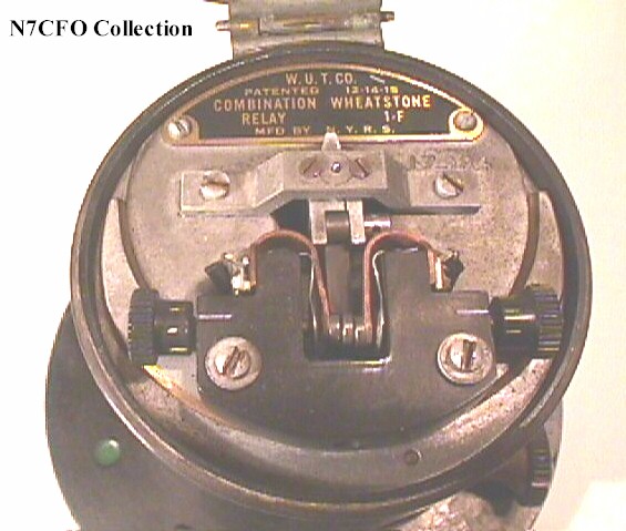
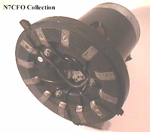
Used interchangeably with polar relay 17-B for operation of polar high speed telegraphic circuits. A U-shaped armature set on its side with horizontal legs bent back into a half circle within which two vertical spools are set. Each spool has from three to five windings for main and artificial lines, and local circuits. Armature consists of thin vertical spindle with field pieces at top and bottom and tongue at top. Base of relay is a relay mounting 2-A, on which is set a cylindrical composition dust cover with hinged glass cover to give access to armature and points.
| Type | Usage | Number of windings per spool |
| COMB. 1-A, 1-B*
1-C, 1-D, 1-F |
General Use | 4--main, artificial, accelerating and opposing. |
| 3-A, GND CORRECTOR. | Relay Ground Correction | 3-main, 2 auxiliary, (one on each spool) |
| 4-A | Superposed Universal Repeaters | 5- 2 main, 1 artificial, accelerating and opposing |
Dia--5 ˝", Ht--5 1/4".
*An older type 1-B (without the word "Combination") had only the main and artificial windings. Relay type 2-A had no permanent magnet, but was energized from a local winding.
These items are grouped here for convenience. Each item must be ordered separately, and is listed separately.
Resonator 3-A, now obsolete, can be converted to 7-A by addition of one Resonator Extension Arm.
Resonator 5-B is used on desks, etc. where portability is desired.
Resonator 6-B is used on tables having flat belt equipment. Resonator 7-B is used on non-belt or V-belt tables.
Arm, Resonator Extension. An iron arm similar to center arm of 7-B resonator. L--10". Ht--2 3/4".
Block, connecting, 7-B. Used to terminate resonator cord on duplex positions. Composition base with three 3 pairs of screw type posts and a metal "snap" cover. L--2 1/8", W--1", Ht--7/8".
Bolt, Sounder, 2-A. A #8-32 x1 ˝" R.H.I. machine screw, with thumb nut and washer used to fasten sounder into hood.
Cord, Resonator. [Pieces or feet] Piece of standard #18 ga. twisted pair black lamp cord used to connect sounder in resonator to instrument on table. If ordered by "pieces" comes in 5 ft. lengths ready to use.
Hood, Resonator. Used as sounding board for one or two sounders. Triangular wooden box of triangular vertical cross section with one side open. W--7", Ht--7 1/4", D--5".
Resonator, 5-B stand only. Iron stand similar to telephone desk stand with flat plate for mounting resonator on. Ht--8", Dia. base--5 1/4".
Resonator, 6-B, frame only. A triangular bracket for attachment to conveyor structure, two additional swivel arms, and a swivel plate for bottom of hood.
Resonator, 7-A, frame only. A triangular base with shaft at top for first swivel arm, three arms, and a swivel plate for hood. Shipping size 12" x 7" x 3".
Resonator, 7-B, frame only. Used on various Morse tables. See description above.
*1-A type did not have "zero" stud on 600 ohm dial and some have wood case. 1-B type is almost similar to 1-C. 1-BB type is made from an older rheostat #17 type, which see. All three are interchangeable in use.